
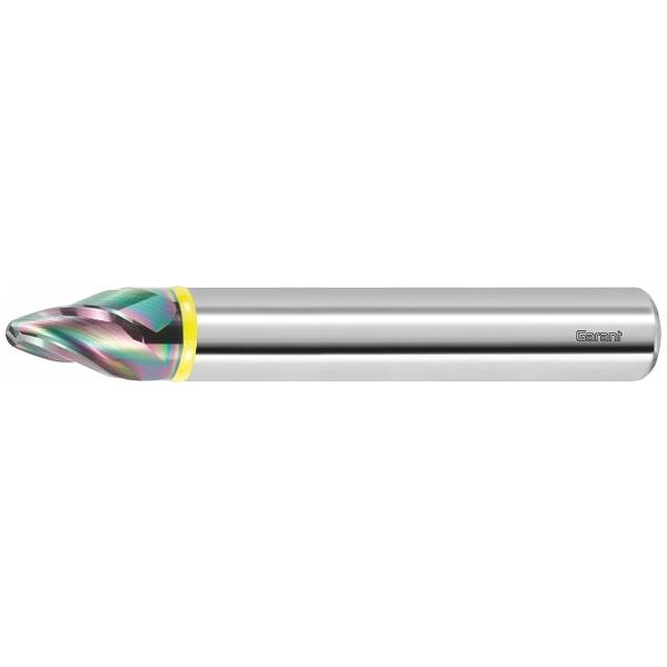

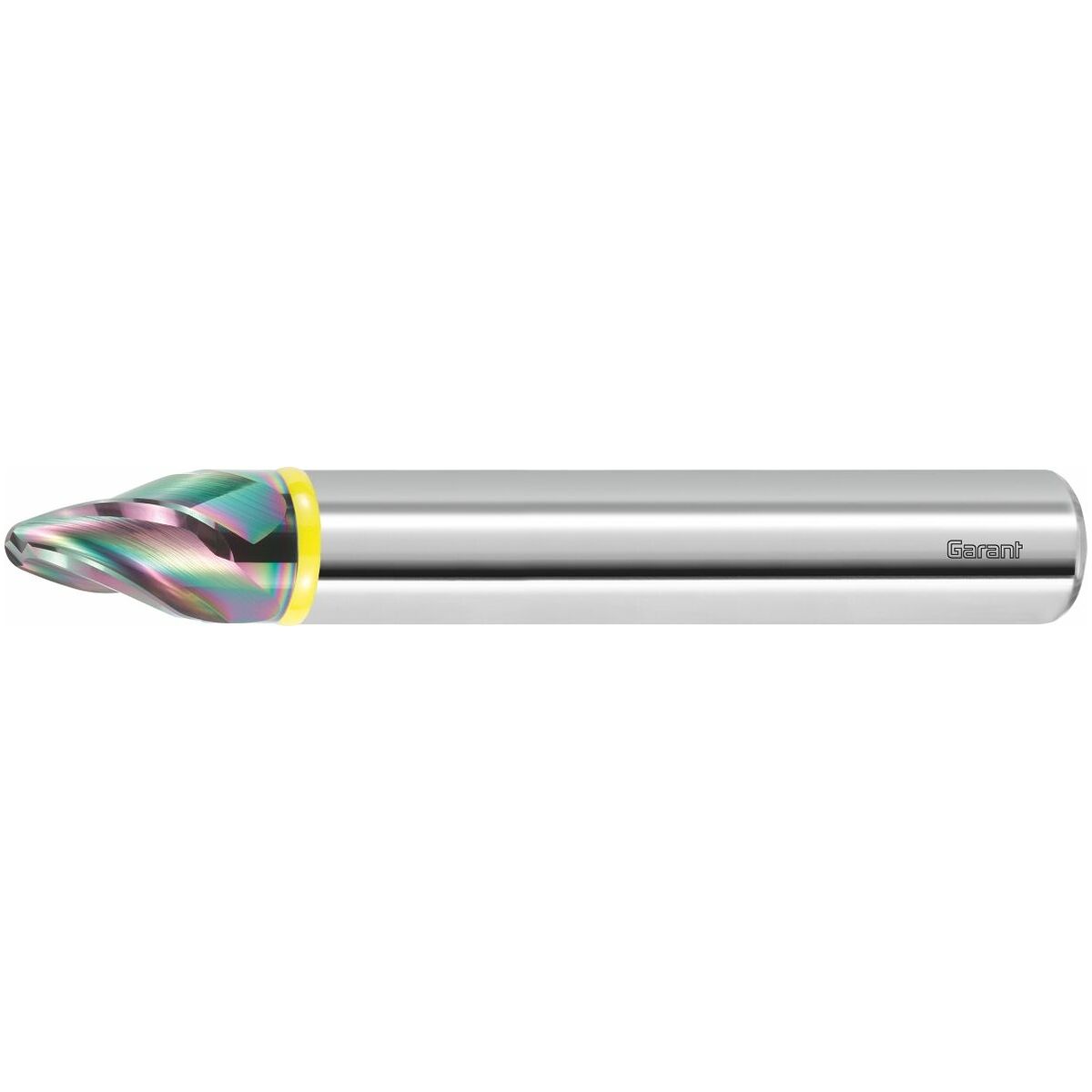
{{ name }}
Article no. {{ combinedCodeWithHighlight }}
Article code:
EAN / GTIN:
Manufacturer number:
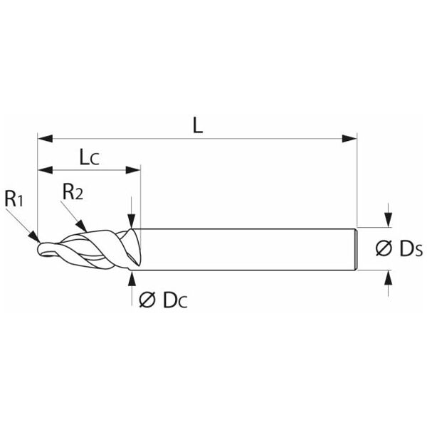
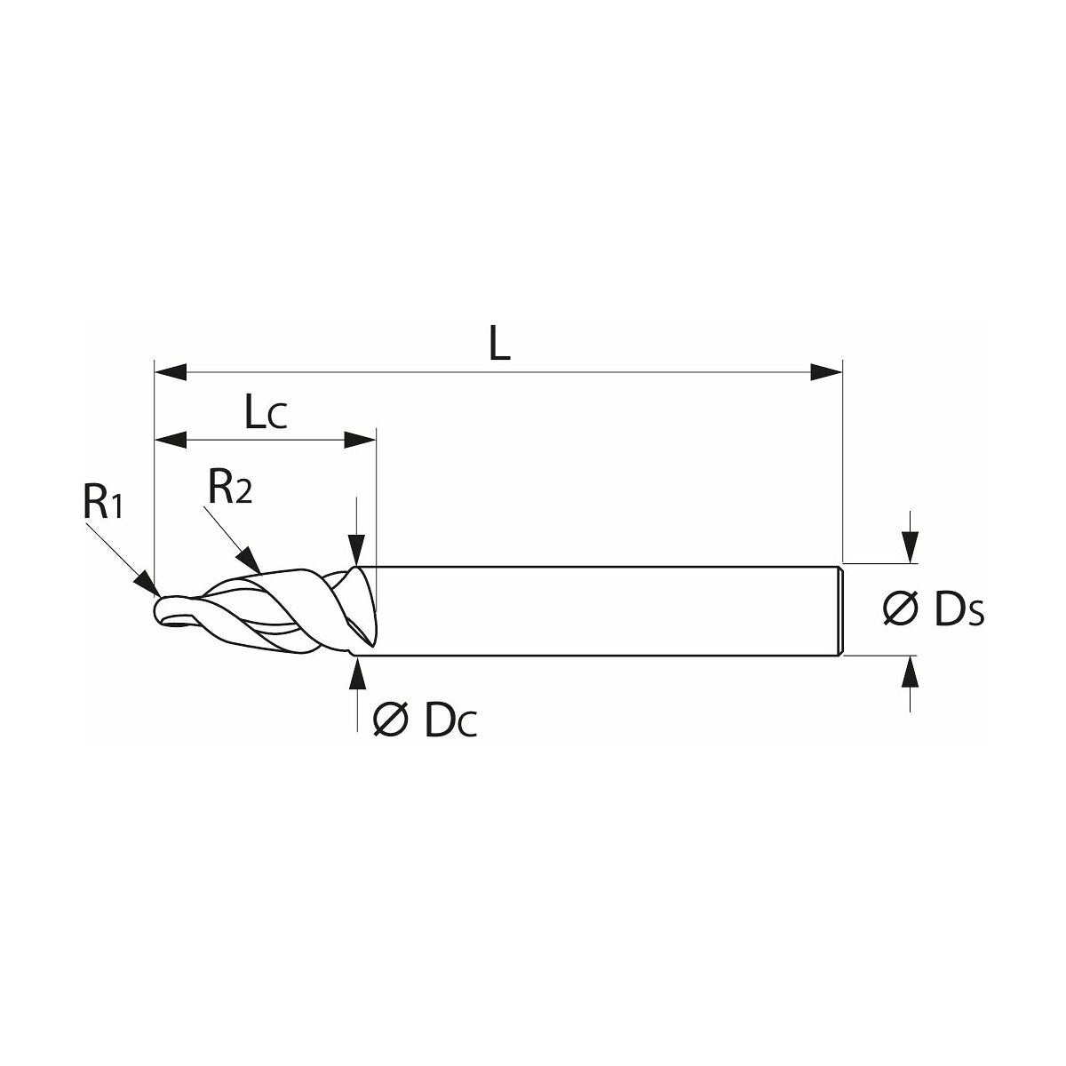
| Cutting edge ⌀ DC | 12 mm | |
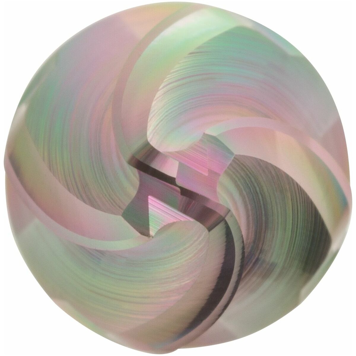
| Coating | DLC | |
| Tool material | Solid carbide | |
| Standard | Manufacturer’s standard | |
| Type | N | |
| Tolerance nominal ⌀ | f8 | |
| No. of teeth Z | 4 | |
| Helix angle | 30 degrees | |
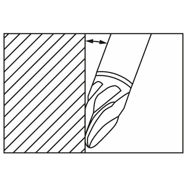
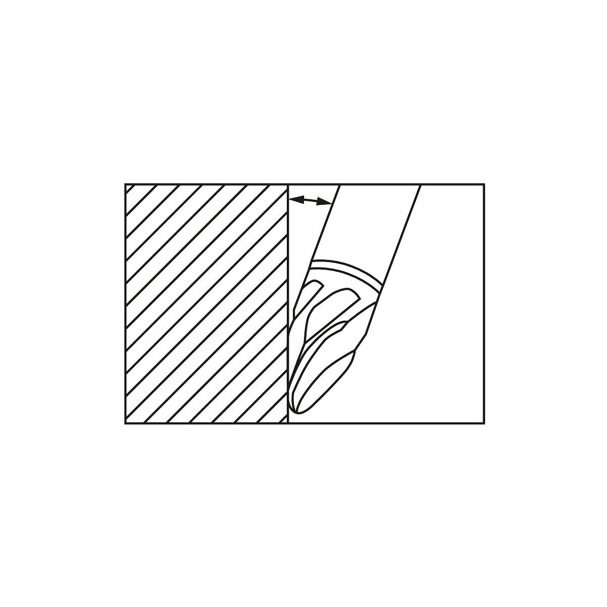
| Direction of infeed | horizontal | |
| Cutting width ae for milling operation | 0.05×D for side milling; 0.05×D for copy milling | |
| Shank | DIN 6535 HA to h6 | |
| Through-coolant | no | |
| Machining strategy | PPC | |
| Flute length Lc | 22 mm | |
| Effective radius R2 | 500 mm | |
| Corner radius R1 | 3 mm | |
| Overall length L | 90 mm | |
| Shank ⌀ Ds | 12 mm | |
| Feed fz for side milling in short-chipping aluminium | 0.07 mm | |
| Feed fz for copy milling in short-chipping aluminium | 0.09 mm | |
| Colour ring | yellow | |
| Type of product | Ball-nosed slot drill |
| Article number |
207529 12/500
Copy |
|
| EAN / GTIN |
4045197989048
Copy |
|
| Manufacturer number |
207529 12/500
Copy |
|
| Manufacturer | Hoffmann Supply Chain GmbH & Co. KG, Poststraße 15, 90471 Nürnberg, Germany, www.hoffmann-group.com |


